In an innovative combination process for the production of pharmaceutical crimp caps, consisting of a deep-drawing process of a laser micro structured metal thin sheet and a back-injection process of the formed metal component, a micro form fitting is used for the bond between plastic and metal. To investigate the achievable bond strength, both the applied laser microstructuring and the injection moulding process parameters are varied. This allows the structure geometry and arrangement to be adjusted and the filling of the back-moulded microstructures to be analysed. Different load cases are tested and a correlation between the microstructure filling and the composite strength is demonstrated.
By Moritz Mascher and Prof. Dr.-Ing. Christian Hopmann, Institute for Plastics Processing (IKV) in Industry and Craft at RWTH Aachen University
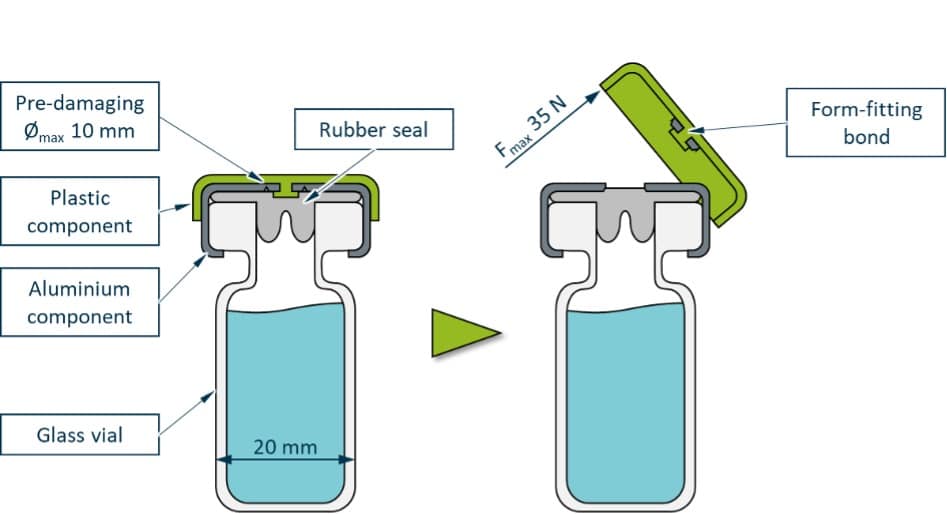
Medical vials and small injection bottles are frequently sealed with so-called crimp caps. These consist of an aluminium component that guarantees a long-lasting seal and a plastic component that allows easy opening of the crimp cap. The function and the current design of the crimp cap including the vial is shown in Fig. 1.
At present, both components are usually produced in separate processes and subsequently pressed together, which necessitates a number of handling and cleaning steps as well as high machine and tooling requirements. At the same time, the potential of the individual materials and their interplay in the hybrid component are only utilised to a limited extent. In order to reduce the manufacturing effort and improve the product quality, a micro form fitting process for joining the plastic with the thin aluminium sheet is developed. In this process, undercut microstructures are incorporated through laser radiation into the metal component, which, during subsequent back-moulding, serve as interlocking elements. The joining of the two components is to be carried out in a combined deep-drawing and back-moulding process, which offers high potential for automation.
For the successful implementation of the process, appropriate materials must be selected, a suitable laser structure must be developed by adjusting the parameters of the laser process such as laser-power and scanning speed. In addition effective process parameters of the injection moulding process must be determined. For this purpose, the laser structure arrangement is systemically varied and a full-factorial analysis of the influence of the injection moulding parameters on the composite of the plastic and aluminium components is carried out. Furthermore, the micro structure filling is evaluated with various measurement methods and correlated with mechanical tests. Finally, laser processing is used to develop a pre-determined breaking point for opening the crimp cap, which qualifies the product for the desired application.
The geometrical boundary conditions and requirements for the crimp cap are standardised in ISO 8362-6 and ISO 8362-7 and provide the boundary conditions for the research results presented [NN11a, NN11b]. For example, the sheet thickness and the shape of the plastic component are specified. In addition, sterilisability of the crimp cap by means of steam sterilisation is required. The crimp cap is opened during use by lifting the plastic component with the thumb. This exposes a rubber stopper in the glass ampoule, which can be pierced with a needle. The bond area between the plastic and the sheet component is limited by the pre-damaging, as a firm bond between the two components must be achieved in the area within the pre-damage and has a maximum diameter of 10 mm, see Fig. 1.
For the ampoule of nominal size 20 considered in this work, i.e. a crimp cap diameter of 20 mm, the maximum force for lifting the plastic component from the rest of the cap must not exceed 35 N to ensure that the cap can be opened in everyday use [NN11a].
Development of a suitable microstructure geometry and arrangement using laser processing
For the production of the microstructured aluminium sheets, a sheet coil is provided by Aluminium Féron GmbH & Co. KG, Düren, Germany. The material-specific requirements for the aluminium and plastic components of the flared cap are specified in DIN EN ISO 8872 [NN03]. The used aluminium component is the aluminium alloy AlFeSi (EN AW-8011A) with the product designation Feraflex TA 200 fl. This is further processed into blanks at the ILT, Aachen, Germany. For this purpose, a single-mode fibre laser of the type Rofin FL 020 C from Coherent Inc., Santa Clara, California, USA, is used, which is especially suitable for classic cutting and welding applications. The laser has a maximum power of 2,000 W, a laser wavelength of 1,070 nm and generates a spot diameter of 45 µm at the focus. The positioning and focusing of the laser radiation on the sheet metal coil is achieved with the aid of a ƒ-theta lens of the type S4LFT1330/328 from Sill Optics GmbH & Co. KG, Wendelstein, Germany, in combination with an intelliSCAN SE20 galvanoscanner from Scanlab GmbH, Puchheim, Germany. With the help of the ƒ-theta lens, it is ensured that the laser radiation impacts the sheet metal coil exclusively perpendicularly during processing in the required working area of 10 x 10 mm2, so that all microstructures are introduced perpendicularly to the sheet metal surface.
Preliminary tests on suitable laser parameters for fabrication of the microstructures show that an optimum microstructure can be obtained by using a circularly arranged line structure as well as a laser power of 1,005 W, a laser speed of 15 m/s and 2 passes of the structure. At these settings, the sheet component, which is 200 µm thick, is not irradiated and a structure depth of approximately 130 µm is achieved. By adjusting the laser parameters, the extent of the linear pre-damage around the microstructure can also be adjusted, which represents a predetermined breaking point for opening the cap. The laser processing of the entire structuring as well as the cutting out of the metal sheets and the introducing of the pre-damaging takes less than 1 sec.
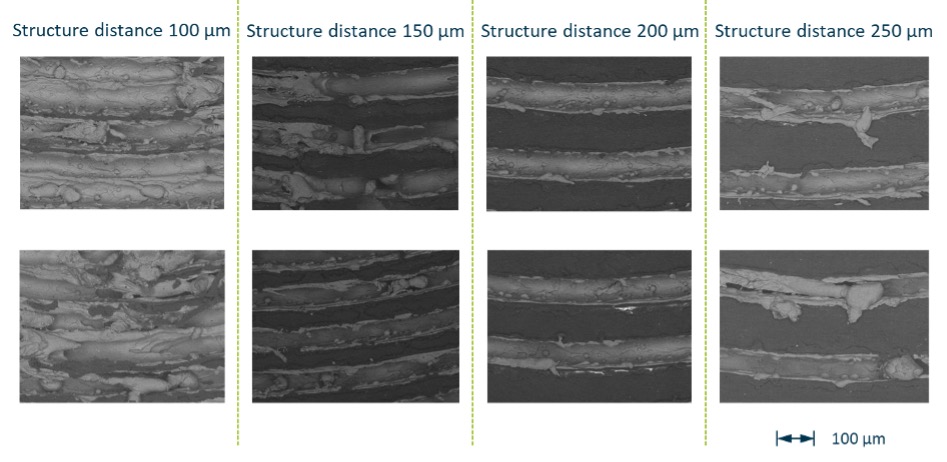
Once the laser parameters have been defined, the microstructure arrangement must then be determined to maximise bond strength. A maximum outer structure diameter of 10 mm is specified by the standards applicable to crimp caps. At the structural centre, the diameter is limited by the laser process. For small structure diameters, the time between the laser passes at one point is reduced, which leads to an increased heat input. In addition, smaller radii lead to accuracy problems with the laser movement, more precisely the multiple passes of a structure, which is realised via a mirror system, resulting in inaccurate structure widths and depths. Currently, a minimum radius of 1.9 mm is achieved. A suitable structure spacing must be defined within the above-mentioned range. The objective here is the smallest possible structure spacing and thus a high density of anchoring elements with simultaneous high structure reproducibility. For this purpose, circular microstructures with different structure spacings between 100 and 250 µm are produced and analysed using laser scanning and electron scanning microscopy. The electron scanning microscope images are shown in Fig. 2 to illustrate the defects of the microstructure geometry at small structure distances due to the excessive heat input.
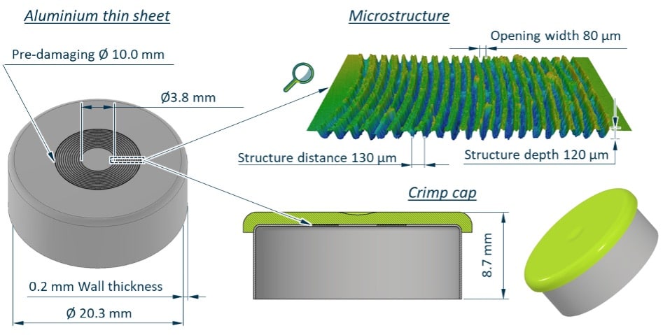
The narrower the structure spacing can be selected, the higher the cumulative structure length in the joint area, which leads to more anchoring possibilities for the plastic component and thus to a higher achievable bond strength. However, if the structure spacing is too small, neighboring structures will be affected by the high temperatures generated by the laser process, see Fig. 2, left. By using pause times between the individual passes in the laser process, reproducible microstructures can be produced with a minimum structure spacing of 130 µm. Based on these investigations and the specifications of the standards ISO 8362-6 and ISO 8362-7 [N11a, NN11b], the final moulding geometry of the pharmaceutical crimp cap, including the final microstructuring, is determined as shown in Fig. 3.
Manufacture of the hybrid crimp caps – material, machine and mould technology used
For the plastic component, the semi-crystalline thermoplastic PP PCGR40 from SABIC AG. Riyadh, Saudi Arabia, is used. The PP is especially suitable for applications in the health care sector and complies with the regulations for contact with food as well as the relevant specifications of the United States Pharmacopoeia, which defines quality standards with regard to strength, purity and consistency of the materials used in the medical and pharmaceutical industries. The manufacturer explicitly mentions the excellent demouldability and good processability at low melt temperatures as process-related advantages of the material [NN22].
This results primarily from the material’s high MFR value of 40 g/10 min, which indicates low-viscosity flow behaviour [FS17]. The aluminium component is microstructured according to Fig. 3. To evaluate the bond strength, however, no pre-damage is initially introduced, otherwise the failure of the pre-damage and not the bond strength is tested.
The flared caps are produced from the laser-cut round metal sheets using a combined deep drawing and back injection process described above on a fully hydraulic KM 110-380 CX injection moulding machine from KraussMaffei Technologies GmbH, Munich, Germany. The machine is equipped with a compact two-platen clamping unit and allows a maximum clamping force of 1,100 kN. The plasticising unit is operated with an open nozzle and has a screw diameter of 25 mm with an L/D ratio of 26. A maximum injection pressure of 2,500 bar and a maximum injection volume flow of 74 cm³/s are possible. In addition, the machine is equipped with a linear robot of the LRX100 series from the same company, which is to take over the insertion of the blanks as well as the removal of the finished flanging caps in fully automatic operation.
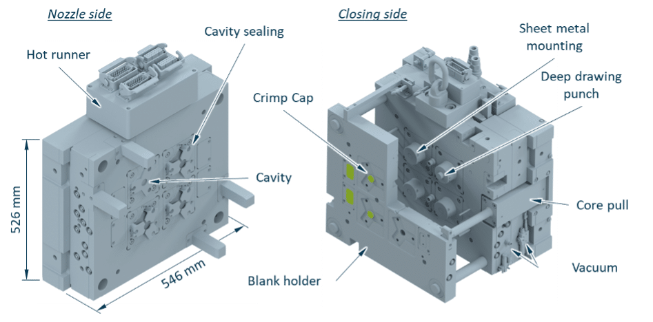
Fig. 4 shows the used 4 cavity injection mould for the combined deep drawing/back injection moulding process. The sheet metal rods are fixed in the mould by means of a vacuum. The blankholder is moved to retain the aluminium thin sheets and apply the necessary pressure for the deep-drawing process. Next, the sheet metal rods are formed into the desired cap geometry by the advance of the deep drawing punch. The mould movements are realised by core pulls. In addition, a sealing concept is provided to seal the cavity from the drawing gap. After the deep-drawing process, the microstructure is back-moulded. The mould was manufactured by Siegfried Hofmann GmbH, Lichtenfels, Germany, and attention was paid to scalability of the mould concept to more cavities during the mould design.
Testing the bond strength for different load cases
In order to investigate the influence of the injection moulding parameters on the composite strength of the plastic and metal components for two different load cases (pull and peel), the parameters from Tab. 1 are investigated using a full-factorial experimental design. In order to evaluate the bond strength, no pre-damage is introduced into the metal component. 16 crimp caps are produced per test point. 8 caps each are tested on the one hand in an angled pull off test, which simulates the use case (opening the vial), and on the other hand in a straight pull off, which is similar to a head pull off test.
| Parameter | (-) | (+) |
| Injection rate (vinj) [cm3/s] | 10 | 20 |
| Holding pressure (pholding) [bar] | 100 | 200 |
| Mould temperature (Tmould) [°C] | 30 | 60 |
| Melt temperature (Tnozzle) [°C] | 230 | 250 |
The investigation of the bond strength is carried out on a tensile testing machine of the type AllroundLine Z10. In its design as a table-top testing machine, it is particularly suitable for tests with low forces or for tests in which only low to medium specimen strains occur. It is designed for a maximum test load of 10 kN and allows a test speed range between 0.0005 and 2,000 mm/min. For testing the flare caps, the test speed is selected to be 100 mm/min according to DIN EN ISO 8872 [NN03]. The pull off force is measured with the aid of a Load Cell Xforce HP force transducer with a nominal force of 200 N and a sensitivity of 2 mV/V. The testXpert II testing software is used for machine control, configuration of the test program and evaluation of the results. All the above-mentioned components of this test system are provided by ZwickRoell AG, Ulm, Germany.
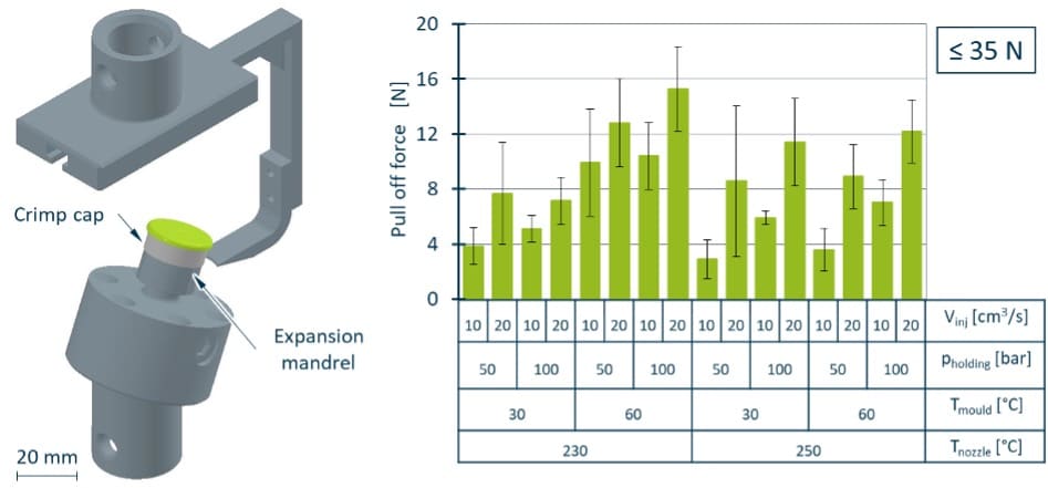
The angled pull off test is performed in accordance with DIN ISO 10985 and represents the load case (peel) of the product application [NN09]. The test setup is shown in Fig. 5 on the left. Due to the angled pull off, a tensile and a peel load are superimposed on the joint.
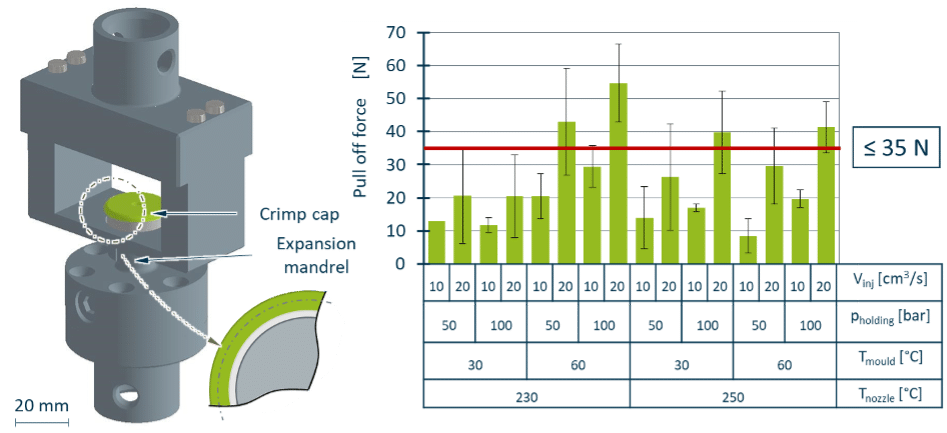
In order to evaluate the load case dependence of the bond strength, an additional straight pull off test comparable to a head tensile test is performed (Fig. 6, left).
The maximum angled pull off force of 15.3 ± 3.1 N is achieved an injection rate of 20 cm³/s, a holding pressure of 200 bar, a mould temperature of 60 °C, and a cylinder temperature of 230 °C.
Similar high pull off forces can be achieved for the other test points with high injection speeds and holding pressures. The minimum pull off force of 2.9 ± 1.4 N is measured at an injection rate of 10 cm³/s, a holding pressure of 100 bar, a mould temperature of 30 °C and a cylinder temperature of 250 °C.
In Fig. 6, the pull off force of the plastic component for the vertical cap pull off is shown on the right. As in the angled pull off, the maximum pull off force of 54.7 ± 11.8 N is achieved at an injection velocity of 20 cm³/s, a holding pressure of 200 bar, a mould temperature of 60 °C and a cylinder temperature of 230 °C. In the straight pull off, the highest bond strengths are achieved at high holding pressures and fast injection speeds. The same trends can be identified in comparison to the angled pull off, which speaks for the reproducibility of the influences investigated.
The minimum pull off force of 8.4 ± 5.2 N is measured at an injection speed of 10 cm³/s, a holding pressure of 100 bar, a mould temperature of 60 °C and a barrel temperature of 250 °C. The pull off forces of the other test points with low injection speeds are comparably low.
An effect analysis is carried out for a evaluation of the individual influence parameters. The greatest effect on the pull off force is the increase in injection speed of 4.1 N for the angled pull off and 17.5 N for the vertical pull off (see Fig. 7). The second largest effect of 3.8 N for the angled pull off and 11.5 N for the vertical pull off is the change in mould temperature. For the injection speed and the mould temperature, a significance of 95.0 % is averaged for both tests. The effect of the change in holding pressure is somewhat lower for both test methods, with 2.3 N for the oblique and 8.2 N for the vertical pull off. The only negative effect can be determined for the temperature increase of the cylinder; it amounts to -1.80 N for the angled and -2.1 N for the vertical pull off. In both tests, both holding pressure and cylinder temperature show no significance in the range of 90.0 % to 99.9 %. The assumption that increasing all four setting parameters results in an increase in the pull off forces can only not be confirmed for the cylinder temperature.
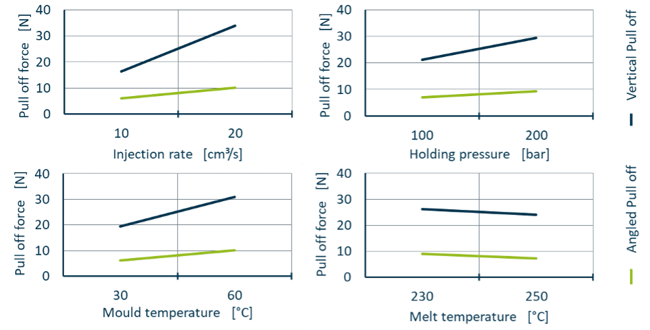
It is clear that significantly greater pull off forces are measured in the vertical test than in the angled test. This applies without exception to each of the 16 test points, with the forces differing by a factor of 2.1 to 4.8. The higher pull off force can be explained by the fact that in the vertical cap pull off, in contrast to the angled test, no peel load acts to superimpose the tensile load. Due to the peel load introduced on one side, the pull off force does not act over the entire composite surface, but lifts the plastic component out of the microstructured aluminium, whereas in the vertical test the entire joint surface counteracts the load immediately with the start of the force application.
Correlation of the bond strength with the microstructure filling
For the optical examinations a confocal laser scanning microscope (LSM) VK-X210 from Keyence Corporation, Osaka, Japan, is used, with which the surface structures of the aluminium and plastic components and thus the microstructure fillings can be visualised. The microscope is equipped with an interference lens of the type CF IC EPI Plan DI from Nikon Corporation, Chiyoda, Tokyo, Japan, which enables a 10-fold magnification of the samples. The software Analysis Application VK-H1XAE version 3.1.1 from Keyence is used to analyse the recorded images. Due to the previous destructive mechanical testing, the aluminium and plastic components are separated and can therefore be examined by means of the LSM. All 16 test points are evaluated.
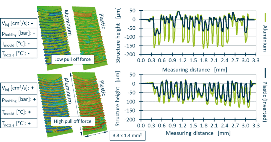
Fig. 8 shows the structural replica measured by LSM for the test point with the lowest and with the highest bond strength achieved. It can be seen that, depending on the used injection moulding parameters, there are significant differences in the depth of the structure filling and the structure filling correlates with the pull off force.
Insertion of a pre-determined breaking point for opening the crimp cap
In the previous investigations, crimp caps without a pre-determined breaking point were examined in order to be able to evaluate the bond strength of the two components. However, a pre-damaging is necessary to open the cap and thus enable the cap to be used for pharmaceutical ampoules. The degree of pre-damage must be adjusted by adjusting the depth of the structure and suitable for the application. The pre-damage must be strong enough to allow safe opening of the crimp cap but at the same time prevent unintentional opening.
The microstructure is first introduced into the aluminium rounds with the previous mentioned laser parameters, after which a further, deeper structure line is generated as pre-damage around the outside of the microstructure by varying the three parameters of power, scanning speed and number of passes. Seven pre-damages and thus seven test points are examined, the assignment of which is shown in Tab. 2.
| Trial point [-] | Passes [-] | Scanning velocity [m/s] | Laser-power [%] |
| High pre-damaging | |||
| 1 | 4 | 15 | 69 |
| 2 | 4 | 10 | 60 |
| 3 | 5 | 15 | 60 |
| Central test point | |||
| 4 | 4 | 15 | 60 |
| Weak pre-damaging | |||
| 5 | 4 | 15 | 51 |
| 6 | 4 | 20 | 60 |
| 7 | 3 | 15 | 60 |
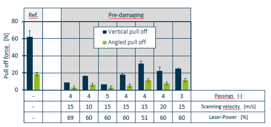
For the production of the pre-damaged crimp caps, the injection moulding parameters with the highest bond strength are selected. The values thus amount to an injection rate of 20 cm³/s, a holding pressure of 200 bar, a mould temperature of 60 °C and a cylinder temperature of 230 °C. The results of the mechanical tests are shown in Fig. 9. The pre-damaged blanks are compared with a non-pre-damaged reference. Despite the same test conditions, the non-pre-damaged reference shows higher bond strengths for the straight (+14 %) and angled (+23 %) pull off than the previous tests (see Fig. 5, Fig. 6). This is due to slight irregularities in the laser process and thus in the microstructure geometry. For the angled cap pull off, the highest pull off force of 11.6 ± 5.0 N is obtained, as expected, for a test point with weak pre-damage, while the lowest pull off force of 2.9 ± 0.1 N is present for severe pre-damage. For vertical pull off, a qualitatively similar distribution of pull off forces is obtained across the test points. Here, too, the highest pull off force of 30.8 ± 3.2 N is present in the case of weak pre-damage, while the lowest pull off force of 6.5 N is attributable to a severely pre-damaged specimen. Changes in the laser parameters power and number of passes have a particularly strong effect, as these have a significant influence on the microstructure depth.
Conclusion and Outlook
The production of microform-fitted plastic/aluminium flanged caps process using a multi-cavity mould can be successfully implemented so that automated production of the hybrid, microform-fitted crimp caps can be achieved. A suitable process window for sufficient bond strength to open the flare caps is determined for the combined deep drawing and back injection moulding process by means of a full-factorial investigation of the injection moulding parameters, and their influence on the composite strength of the hybrid components is assessed with the aid of the plastic component pull off forces. The injection speed and mould temperature have the greatest positive effect. Only for the melt temperature does an increase in the parameter lead to a reduction in the pull off forces. The maximum pull off forces measured for the investigated plastic moulding compound indicate that the composite strength is adequate for the application. The maximum permissible pull off force of 35 N is not exceeded when a pre-damaging of the crimp cap is applied. Microscopy images over several test points indicate that the bond strength correlates strongly with the structural filling level of the microstructured aluminium; for the process point with the highest bond strength, an averaged filling level of 89 % is determined with uniform filling of all structures.
In the future, minor revisions can be made to the injection mould, e.g. an improvement in the centring of the sheet metal, to improve process reliability. In addition, the manufactured crimp caps are to be subjected to sterilisation and the influence of the crimping on the bond strength is to be tested.
Acknowledgements
The project that serves as a basis for this report was financed with funds from the Federal Ministry for Education and Research under funding number 03XP0291. Furthermore, we would like to express our gratitude to the Fraunhofer Institut für Lasertechnik (ILT) and our project partners from the industry (KraussMaffei Technologies GmbH, Siegfried Hofmann GmbH, Pulsar Photonics GmbH, SimpaTec Simulation & Technology Consulting GmbH, Röchling SE & Co. KG).
References
[FS17] Frick, A.; Stern, C.: Einführung in die Kunststoffprüfung. Prüfmethoden und Anwendungen. München: Carl Hanser Verlag, 2017
[NN03] N.N.: Aluminium caps for transfusion, infusion and injection bottles — General requirements and test methods. Geneva: International Organization for Standardization, 2003
[NN09] N.N.: Bördelkappen aus Aluminium-Kunststoffkombinationen für Infusions- und Injektionsflaschen – Anforderungen und Prüfverfahren (ISO 10985:2009). Berlin: DIN Deutsches Institut für Normung e. V., 2009
[NN11a] N.N.: Injektionsbehältnisse und Zubehör – Teil 6: Bördelkappen aus Aluminium-Kunststoffkombinationen für Injektionsflaschen (ISO 8362-6:2010); Deutsche Fassung EN ISO 8362-6:2011. Berlin: DIN Deutsches Institut für Normung e. V., 2011
[NN11b] N.N.: Injektionsbehältnisse und Zubehör – Teil 7: Bördelkappen aus Aluminium-Kunststoffkombinationen für Injektionsflaschen ohne überstehendes Kunststoffteil (ISO 8362-7:2006); Deutsche Fassung EN ISO 8362-7:2010. Berlin: DIN Deutsches Institut für Normung e. V., 2011
[NN22] N.N.: SABIC® PP PCGR40 – Global Technical Data Sheet. Riad, Saudi-Arabien: SABIC AG, Riad, Saudi-Arabien, 2022
Symbols
| Symbol | Unit | Description |
| Vstart | cm3 | Start Volume |
| Tmould | °C | Mould Temperature |
| pholding | bar | Holding pressure |
| vinj | cm3/s | Injection rate |
Abbreviations
| Notation | Description |
| Al | Aluminium |
| Fe | Iron |
| IKV | Institute for Plastics Processing in Industry and Craft at RWTH Aachen |
| ILT | Fraunhofer Institute for Laser Technology |
| inj | Injection |
| LSM | Laser scanning microscope |
| MFR | Melt flow rate |
| PP | Polypropylene |
| Si | Silicon |
Secondary publication of the paper presented at 32nd International Colloquium Plastics Technology, Institute for Plastics Processing (IKV) in Industry and Craft at RWTH-Aachen University, 28-29 February 2024, Aachen/Germany
Kontakt
Institute for Plastics Processing (IKV) in Industry and Craft at RWTH Aachen University
D-52074 Aachen
moritz.mascher@ikv.rwth-aachen.de
www.ikv-aachen.de